BUSBOOT · TYPE 01 to TYPE 16 · to 36 kV
BUSBOOT: one shroud family, PVC or cross-linked polyolefin
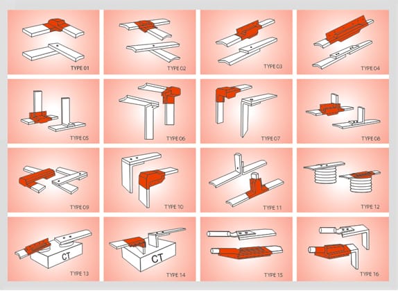
The drawing sheet numbers sixteen connection types. Pick the type first, then read the wall off the table for your material: 3.00 mm of PVC at 24 kV, 1.8 mm of polyolefin.
BUSBOOT busbar insulating shroud
A moulded cover that goes over a busbar connection after somebody else has bolted and torqued it, and lifts off again for the next check. It is published in two materials against the same 36 kV ceiling: flexible PVC, which carries the UL file number and the ANSI C37.20.2 switchgear reference, and cross-linked polyolefin, which is halogen free and holds a thinner wall at every voltage the two tables share.
- Two constructions on one 36 kV ceiling, separated by material clause rather than by voltage
- PVC thickness published as a recommended value at five voltages, 3.3 kV to 38.0 kV
- Polyolefin thickness published as a minimum at four voltages, 12 kV to 36 kV
- Fits joints of any shape, tees and elbows included; custom shapes and connections offered on the PVC sheet
- Polyolefin resists acid, alkali and salt corrosion as well as UV and ozone
- PVC published as highly resistant to UV rays and ozone, and suitable indoor or outdoor
- Removable and refittable as often as the joint has to be opened
| Covers | Busbar and switchgear connections up to 36 kV |
|---|---|
| Ordered by | Connection type, TYPE 01 to TYPE 16 on the manufacturer's drawing sheet |
| PVC wall | 1.25 mm at 3.3 kV rising to 4.50 mm at 38.0 kV |
| Polyolefin minimum wall | 1.0 mm at 12 kV rising to 2.5 mm at 36 kV |
| Dielectric strength | PVC 16 kV/mm (min.); polyolefin 22 kV/mm (min.) |
| Continuous temperature | PVC -20 °C to 115 °C; polyolefin -40 °C to +115 °C |
| Halogen content | Polyolefin published halogen free; PVC is not |
| Fitting | Installs, removes and replaces in minutes; the PVC part ships complete with fasteners |
Ordered by connection type, not by bar size
The manufacturer's drawing sheet numbers sixteen shroud types, TYPE 01 through TYPE 16, and in every drawing the shading sits on the joint rather than on the run. Types 13 and 14 are connections made at a box marked CT.
Quote that number on the enquiry. Two joints at the same voltage on the same bar section take different mouldings, and the panel general arrangement is what tells you which of the sixteen a given joint is.
A geometry that is not on the sheet is handled by cutting a mould for it; custom shapes and connections are offered on the PVC sheet. Either way the part goes on over a joint that is already made and comes back off in minutes for a torque check, a thermographic scan or a re-tightening, and that reversibility is the reason to put a shroud on a joint instead of a sleeve.
PVC shroud: recommended wall thickness by system voltage
| System voltage | Wall thickness |
|---|---|
| 3.3 kV | 1.25 mm |
| 12.0 kV | 2.00 mm |
| 18.0 kV | 2.50 mm |
| 24.0 kV | 3.00 mm |
| 38.0 kV | 4.50 mm |
The sheet publishes this table to 38.0 kV while describing the part itself as covering connections up to 36 kV. Take 36 kV as the governing figure and settle the 38.0 kV row with the manufacturer before it enters a specification.
Polyolefin shroud: minimum wall thickness by system voltage
| System voltage | Minimum thickness |
|---|---|
| 12 kV | 1.0 mm |
| 18 kV | 1.4 mm |
| 24 kV | 1.8 mm |
| 36 kV | 2.5 mm |
Four rows, and the lowest is 12 kV — no polyolefin figure is published below that. These are minima, not recommendations, so a part thicker than its row still satisfies it.
The three rows that fork the two sheets
Both sheets stop at 36 kV, so voltage cannot choose between them and these three rows do. The wider material argument, board included, is settled once on busbar insulation material.
| Property | PVC | Cross-linked polyolefin | Test method |
|---|---|---|---|
| Halogen content | Not halogen free | Halogen free | — |
| Continuous operating temperature | -20 °C to 115 °C | -40 °C to +115 °C | IEC 216 |
| Dielectric strength | 16 kV/mm (min.) | 22 kV/mm (min.) | ASTM D149 |
Where a halogen clause picks the polyolefin sheet
Halogen content is a yes-or-no line in an enclosure specification rather than a figure to be traded against the 6 kV/mm the polyolefin part gains on dielectric strength. Three places that line usually appears:
- Enclosed panels and switchrooms, where whatever burns does so inside the volume an operator has to open.
- Tunnels and underground substations, where the smoke clause is written before any wall thickness is.
- Marine and offshore switchboards, where the restriction sits in the build standard and is not negotiated per line item.
- Neither sheet publishes a smoke-density or acid-gas figure, so such a clause is met by the halogen-free statement itself and by nothing measured. Say that plainly in the submittal.
- Chemical exposure is a separate axis. The polyolefin sheet publishes resistance to acid, alkali and salt corrosion alongside UV and ozone; the PVC sheet publishes UV and ozone resistance and states the part is suitable indoor or outdoor.
PVC shroud: measured properties
| Test description | Recorded value | Test method |
|---|---|---|
| Dielectric strength | 16 kV/mm (min.) | ASTM D149 |
| Tensile strength | 12 N/mm² (min.) | ASTM D638 |
| Elongation | 350 % (min.) | ASTM D638 |
| Density | 1.23 gm/cm³ | ASTM D792 |
| Hardness | 65 ± 5 Shore A | ASTM D2240 |
| Continuous operating temperature | -20 °C to 115 °C | IEC 216 |
| Flammability | Pass | UL 94-V0 |
Polyolefin shroud: physical properties
| Test description | Recorded value | Test method |
|---|---|---|
| Tensile strength | 9 N/mm² (min.) | ASTM D638 |
| Ultimate elongation | 300 % (min.) | ASTM D638 |
| Water absorption | 0.5 % (max.) | ASTM D570 |
| Hardness | 45 ± 10 Shore D | ASTM D2240 |
Polyolefin shroud: thermal properties
| Test description | Recorded value | Test method |
|---|---|---|
| Low-temperature flexibility, -40 °C for 4 hours | No cracking | ASTM D2671 |
| Heat shock, 90 °C for 30 minutes | No cracking or flowing | ESI 09-11 |
| Continuous temperature limit | -40 °C to +115 °C | IEC 216 |
| Accelerated ageing | Pass | ASTM D2671 |
| Tensile strength | 10 N/mm² (min.) | ASTM D638 |
| Ultimate elongation | 250 % (min.) | ASTM D638 |
| Shrink temperature | 125 °C | IEC 216 |
Tensile strength and ultimate elongation appear twice on the published sheet: 9 N/mm² and 300 % under the physical heading, then 10 N/mm² and 250 % here. Both pairs are reproduced as printed rather than relabelled. The shrink-temperature row sits on the same sheet that describes the part as removable as often as required; confirm it before quoting.
Polyolefin shroud: electrical properties
| Test description | Recorded value | Test method |
|---|---|---|
| Dielectric strength | 22 kV/mm (min.) | ASTM D149 |
| Volume resistivity | 1 × 10¹³ Ohm·cm (min.) | ASTM D257 |
| Dielectric constant | 5 (max.) | ASTM D150 |
| Resistance to tracking and erosion | No tracking, erosion or flame failure up to 3.25 kV for 20 min. | ASTM D2303 |
Every method named in the third column of these four tables is decoded once, on busbar insulation standards.
Where the UL file number is published
UL File E335936 and the ANSI C37.20.2 switchgear reference are printed on the PVC shroud sheet. The polyolefin sheet publishes ASTM, ESI and IEC methods and does not repeat the file number, although the manufacturer's own certification history records the 2011 file against Busboot and Bustube. So a clause reading UL listed is answered by citing the PVC part, and moving the same line item to polyolefin for a halogen clause is a substitution to be confirmed rather than a like-for-like swap.
Where this part sits
- Busbar connectionsThe seven joint geometries behind the sixteen type numbers, and which of them a shroud cannot take.
- Busbar insulation materialPVC against cross-linked polyolefin against GBBS board, on one table, for the whole range.
- Heat-shrinkable bus sheetWhat covers a made-up joint that matches no moulding on the drawing sheet.
- Busbar sleeve size chartCodes for the straight run either side of the joint. The shroud is not sized from it.
- Cutting busbar air clearanceWhere the wall thickness above is spent, and the millimetres that come back as panel width.
- Busbar insulation standardsANSI C37.20.2, IEC 216, ESI 09-11 and the ASTM methods, decoded once.
- Shrouds inside an assembled MV panelThe part in place, on the joints of a panel that has been built.
What this page does not establish
A BUSBOOT covers a connection somebody else made and torqued. Nothing on either sheet fixes the contact resistance of that joint, the bolt torque it was assembled to, or the current the bar underneath can carry. Those are busbar design figures, and no row above answers them.
Send the type number and the voltage
Four fields close the enquiry: the connection type from the drawing sheet, the system voltage, the bar section in millimetres, and the material clause if the project carries one.