Method hub · GSC to GEHB
Five ways to insulate a busbar, and when each is right
Geometry picks the part, voltage picks the wall. Four of the five reach 36 kV and the fifth carries no voltage rating at all.
What the geometry decides, and what the voltage decides
Geometry picks the part; voltage picks the wall inside it. A sleeve goes on a run, a shroud or a sheet on a joint, a cap on an end, a board in the gap between phases.
The reason to cover a bar at all is dimensional. The manufacturer publishes 140 mm phase-to-phase at 36 kV on Heavy Wall sleeve against 320 mm for the same bar left bare under IEC 71-2, and those 180 mm come back as panel width, copper length and sheet metal.
A straight run and a bolted joint rarely take the same part. The sleeve is a continuous tube supplied on reels of 1.5 to 100 m and specified for straight or angled bars; the bus sheet is specified for joints of almost any size or shape — tees, elbows and connections where tubing and tape cannot be used.
Two of the five are heat-recovered and three are mechanical, and that split decides the outage rather than the price. The sleeve recovers at 125 °C and the bus sheet goes on with the same gas torch or hot air gun, so both want the bar dead; a shroud, a cap and a board go on and come off by hand or by fastener, which is what you want over a joint you will open again for a torque check.
The five methods on one row each
Read the geometry column first: four of the five reach 36 kV and none of them substitutes for another. The sleeve, the PVC shroud, the bus sheet and the end cap are rated against ANSI C37.20.2 for switchgear; the polyolefin shroud is specified by minimum wall per voltage, and the barrier board carries no voltage rating at all. Every test method behind a measured figure on this site is decoded once on the standards page.
| Method | Voltage ceiling | Wall at the top of its range | Geometry it suits | Removable | Tool to install |
|---|---|---|---|---|---|
| Heat-shrink sleeve (GSC, GMB, GHB) | 3.3 kV GSC · 24 kV GMB · 36 kV GHB | 3.20–4.20 mm across GHB | Straight or angled runs, rectangular or round bar | No | Gas torch or hot air gun |
| Moulded shroud (BUSBOOT) | 36 kV in both materials | 2.5 mm polyolefin at 36 kV · 4.50 mm PVC at 38 kV | Bolted joints, tees and elbows | Yes, repeatedly | None; PVC ships with fasteners |
| Heat-shrinkable bus sheet (GMHS, GHHS) | 17.5 kV GMHS · 36 kV GHHS | 4.0 mm, 5.5 mm with adhesive | Joints where tubing and tape cannot be used | No | Gas torch or hot air gun |
| End cap (BUSCAP, GBC series) | 36 kV | Not published | The end of a live bar | Yes, in minutes | None |
| Barrier board (GBBS) | No voltage rating; 20 kV/mm dielectric strength | 2.0, 3.0 or 5.0 mm sheet | Inter-phase barrier in the cabinet; reduced-clearance structures | Yes | Saw and drill |
The five parts, and the page that specifies each
Each part has its own page here carrying the published dimensions. The manufacturer's family datasheet is Switchgear Insulation Products (PDF).
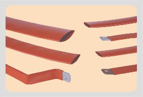
Heat-shrink sleeve
Three wall grades on one geometry: GSC to 3.3 kV, GMB to 24 kV, GHB to 36 kV. Non-tracking cross-linked polyolefin, flexible enough to take an angled bar without creasing. Sized by width plus breadth on rectangular bar and by diameter on round.
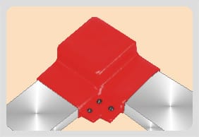
Moulded shroud
One shroud family in two materials sharing a 36 kV ceiling. Polyolefin runs a 1.0 mm minimum wall at 12 kV rising to 2.5 mm at 36 kV; PVC is thicker at every step, 2.00 mm at 12 kV to 4.50 mm at 38 kV, and is UL certified under File E335936.
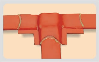
Heat-shrinkable bus sheet
An adhesive-backed sheet for joints a tube cannot follow. GHHS ships 1200 × 430 mm at 4 mm thick; the cut extends a minimum of 100 mm onto each leg and overlaps existing insulation by 65 mm after shrinking, so a 100 mm tee takes a 450 × 325 mm piece and three come out of one sheet.
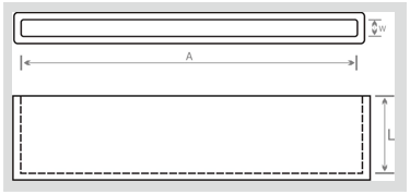
End cap
A flexible, re-usable PVC cap over the end of a live bar, tested to ANSI C37.20.2 for switchgear application to 36 kV. It is the only part here that covers a termination rather than a length, and it installs, removes or replaces in a few minutes.
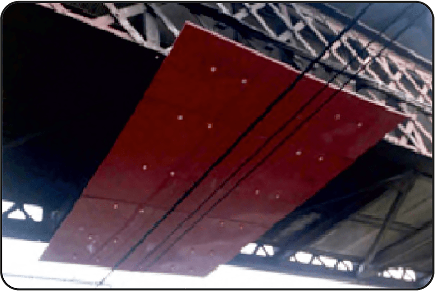
Barrier board
Non-shrinkable polyolefin sheet that stands in the air gap instead of sitting on the conductor: 670 or 970 mm wide, 15 m long, cut and drilled without special equipment. It withstands a power arc without changing shape and wipes clean afterwards with no visible surface damage, which is what makes it an inter-phase barrier rather than a covering.
Halogen free is a polyolefin property here, not a range-wide one
Halogen free is published for the cross-linked polyolefin parts only: all four sleeve series, the polyolefin shroud, the GMHS and GHHS bus sheet, and the GBBS barrier board. The two PVC parts — the PVC shroud and the end cap — carry no such claim, and none should be read into their 36 kV rating. So an enclosure specified halogen-free throughout takes its joints in polyolefin shroud or bus sheet and loses the PVC shroud, even though the two shrouds share a ceiling and the PVC is the thicker wall at 12, 18, 24 and 36 kV alike.
Ten words, four parts
Sleeve, tube and tubing all mean the heat-recovered length that goes over a bar. Shroud, boot and cover all mean the moulded shell over a joint, which the manufacturer also calls a connection shroud and a protection shroud. Guard, shield and barrier point at the board standing in the gap, and cap means the end of the bar and nothing further along it.
Trade names cut across those words again: the sleeve is BUSTUBE, the shroud BUSBOOT, the end cap BUSCAP and the sheet is Bus Sheet. The eight series letters — GSC, GMB, GHB, GEHB, GBC, GBBS, GMHS and GHHS — are what has to appear on the purchase order.
One pair is worth separating rather than treating as loose usage. An insulator is a moulded support that carries the bar's weight and holds the gap open; insulation is a covering on the bar that supports nothing. Which one a drawing is asking for changes the enquiry entirely.
Reading a Gala busbar code
- The number is not a bar size
- GMB 100/38 is 100 mm supplied and 38 mm recovered. The bar it fits is 83 to 126 mm width plus breadth — read that from the size chart, never from the figures in the code.
- GSC
- Thin Wall sleeve, to 3.3 kV. GSC 16/8 to GSC 180/90, wall 0.69 to 1.50 mm, reels of 25 to 100 m.
- GMB
- Medium Wall sleeve, to 24 kV. GMB 16/6 to GMB 250/100, wall 1.70 to 3.30 mm, reels of 1.5 to 25 m.
- GHB
- Heavy Wall sleeve, to 36 kV. GHB 25/8 to GHB 250/120, wall 3.20 to 4.20 mm, reels of 1.5 to 25 m.
- GEHB
- The separate 66 kV series, GEHB 50/20 to GEHB 150/60. The standard sleeve range stops at 36 kV and no one family spans both.
- GBC
- End caps in PVC, GBC1 to GBC18, tested for switchgear application to 36 kV.
- GMHS and GHHS
- The two bus sheet grades. GMHS gives flashover protection to 17.5 kV and GHHS to 36 kV; both are non-tracking cross-linked polyolefin carrying an adhesive layer.
- GBBS
- Barrier board in non-shrinkable polyolefin. GBBS-2, GBBS-3, GBBS-3A and GBBS-5A across 670 and 970 mm widths, 15 m long, 2.0, 3.0 or 5.0 mm thick.
- No code on the shroud
- The shroud family carries no series letters. It is specified by connection shape, voltage and material, and custom shapes and connections are moulded to order.
Where this hub hands off
Each of these owns a decision this page only frames.
- Busbar sleeve size chartEvery GSC, GMB and GHB row: supplied and recovered diameter, wall, reel length, and the bar range each code accepts.
- Choosing between cross-linked polyolefin, PVC and rigid boardMaterial before part number, for the joint where the shroud comes in both and the 36 kV ceiling does not separate them.
- Busbar insulation tape against heat-shrink sleeveThe wrap-versus-recover question, and where a tape is the only thing that reaches.
- Cutting busbar air clearance with insulationThe millimetres at 12, 17.5, 24 and 36 kV, and what the panel recovers in width.
- Seven busbar connection geometries and what covers eachTee, elbow, edgewise turn, riser, tap — matched to shroud, sheet or cap.
- The standards a busbar sleeve is tested toANSI C37.20.2, IEC 71-2, IEC 216 and the ASTM methods behind each measured figure.
- GEHB 66 kV busbar sleeveThe one part above 36 kV, and why it is a separate series rather than a bigger GHB.
What this page does not settle
It settles which part covers which geometry and at what wall. It does not settle what the bar carries once it is covered: temperature rise and derating of an insulated conductor are busbar design questions, and no figure for either is published in the sources this site works from. It does not settle the clearance you may claim on a drawing either — the clearance page holds the millimetres.
Send a bar section and a voltage
Four facts settle a code: width plus breadth or diameter, the system voltage, whether the part sits on a run, a joint or an end, and how many metres or pieces. Send those and the reply names parts instead of asking questions.