Busbar insulation, indexed by dimension
Busbar sleeving, sized in millimetres
Two numbers return a part code: the bar's section in millimetres, then the system voltage that sets the wall grade. Nothing here is sized by current.
- GSC thin wall covers to 3.3 kV, GMB medium wall to 24 kV, GHB heavy wall to 36 kV. The standard range stops there — GEHB is a separate series for 66 kV.
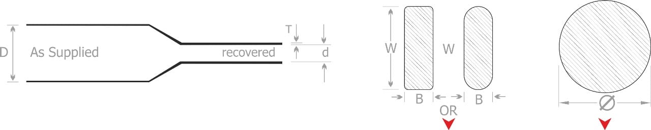
- Rectangular bar is sized on width plus breadth, round bar on diameter, and both columns sit on the same chart row.
- Every part specified here is manufactured by Gala Thermo Shrink Pvt. Ltd. at Palghar, Maharashtra and the Surat SEZ, Gujarat.
The 36 kV case, in millimetres
The three standard wall grades
Voltage picks the grade. Bar section picks the code inside it.
| Series | Voltage | Wall T | Codes | Rectangular bar, W + B |
|---|---|---|---|---|
| GSC thin wall | to 3.3 kV | 0.69–1.50 mm | GSC 16/8 to GSC 180/90 | 16 to 236 mm |
| GMB medium wall | to 24 kV | 1.70–3.30 mm | GMB 16/6 to GMB 250/100 | 11 to 314 mm |
| GHB heavy wall | to 36 kV | 3.20–4.20 mm | GHB 25/8 to GHB 250/120 | 20 to 314 mm |
Find the geometry, then the part
A bar is rarely one section end to end. Work along it and change part where the geometry changes.
A straight run between supports
No bolt heads, no change of section. Pick the grade on voltage, then the code on width plus breadth. Non-tracking cross-linked polyolefin, flexible enough to follow an angled bar without creasing.
A bolted joint you will open again
A shroud is moulded to the joint and comes off with its fasteners, so the connection stays inspectable. BUSBOOT is made in PVC and in cross-linked polyolefin, both to 36 kV: the PVC wall runs 1.25 mm at 3.3 kV to 4.50 mm at 38 kV, the polyolefin 1.0 mm at 12 kV to 2.5 mm at 36 kV.
A tee or elbow nothing moulded fits
Bus sheet is cut flat, wrapped over the geometry and shrunk down with a gas torch or hot air gun. GMHS gives flashover protection to 17.5 kV and GHHS to 36 kV. A GHHS sheet is 1200 × 430 mm at 4 mm thick, 5.5 mm with its adhesive layer, and a 100 mm busbar tee takes a 450 × 325 mm cut — three to a sheet.
The cut end of a live bar
An end cap covers the exposed end face and nothing else. BUSCAP is flexible PVC in the GBC1 to GBC18 range, tested to ANSI C37.20.2 for switchgear application to 36 kV. It pushes on and pulls off in minutes, which is what makes it re-usable rather than consumable.
The air gap between phases
Where the answer is a barrier rather than a covering, GBBS is non-shrinkable polyolefin board: 670 or 970 mm wide, 15 m long, in 2.0, 3.0 and 5.0 mm thicknesses. It cuts and drills with ordinary workshop tooling and withstands a power arc without changing shape.
A bar above 36 kV
The standard range stops at 36 kV. Above it sits one separate extra-heavy-wall series, GEHB 50/20 to GEHB 150/60, meeting ANSI C37.20.2 for switchgear application to 66 kV. It is a busbar sleeve and nothing else — not a cable termination, and no extension of the cable-accessory range.
The reference layer
The chart is the spine. The rest tells you which row of it to read.
- Busbar sleeve size chartEvery GSC, GMB and GHB code, both bar shapes, one table.
- Cutting busbar air clearance with insulationThe bare-against-insulated figures at 12, 17.5, 24 and 36 kV.
- The standards a busbar sleeve is tested toANSI C37.20.2, IEC 71-2, IEC 216, ESI 09-11 and the ASTM methods, decoded once.
- Installing a busbar sleeveMeasure, cut, shrink, inspect.
- Cross-linked polyolefin, PVC or rigid boardWhy one joint is offered in two materials at the same voltage.
- Tape against sleeveThe honest case for winding a bar rather than sleeving it.
- Busbar insulator or busbar insulation?One holds the bar up, the other covers it.
- Seven busbar connection geometriesStraight, lap, tee, elbow and the four that need a cut sheet.
Grade first, then code
IEC 71-2 sets the air clearance a bare conductor needs, and at 36 kV that is 320 mm phase to phase. Put the same bar inside a heavy-wall GHB sleeve and the manufacturer's clearance table gives 140 mm. Those 180 mm are the entire commercial argument for covering a bar, and the clearance page carries the figures at 12, 17.5 and 24 kV as well.
A three-phase cubicle holds two of those gaps side by side, plus the distance out to the earthed enclosure wall. That is why the sleeve and the shroud datasheets both argue compact panel design rather than dielectric strength.
Sizing runs off the section of the bar, never off its current rating. Add width to breadth on a rectangular bar, or take the diameter on a round one, then find the code whose bracket contains that figure. The chart quotes supplied bore D as a minimum and recovered bore d as a maximum, so the sleeve has to clear the bar going on and close under it once shrunk.
Grade is chosen before code, which is why one bar has three answers. A 100 × 10 mm bar sums to 110 mm: thin wall and medium wall each bracket that figure in two codes, heavy wall in exactly one. Same copper, same sum, a different part number at every voltage.
BUSTUBE is the manufacturer's trade name for this sleeve, and the trade-name material sits on the manufacturer's own product page. UL File E335936 covers Busboot and Bustube.
What none of this establishes is whether the bar underneath is the right bar. A sleeve is a dielectric covering laid over a conductor that was sized on temperature rise, and the current an insulated bar can carry is a busbar design question. Nothing on this site revises a rating.
Four numbers return a code
Bar width, bar breadth, run length and system voltage. Add the joint geometry if the run has one, and say whether the panel is indoor or outdoor.