Product · BUSCAP · GBC1–GBC18
What a BUSCAP does at a live bar end
Eighteen moulded PVC sizes, GBC1 for a 15 × 5 mm bar up to GBC18 for 200 × 12 mm. It covers the cut end of a live bar and comes off in minutes when that end has to be reached.
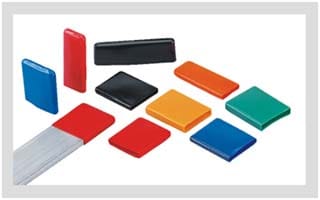
BUSCAP busbar end cap, GBC series
BUSCAP is a flexible PVC cap that covers the end of a live busbar. Eighteen consecutive sizes run from GBC1, for a 15 × 5 mm bar, to GBC18, for 200 × 12 mm, and the cap reaches 20, 30, 50 or 70 mm back along the bar depending on the code. It is tested to ANSI C37.20.2 for medium-voltage switchgear application to 36 kV, and it installs, removes or replaces in a few minutes.
- Covers a square-cut bar end with no tape, no wrap and no heat gun
- Comes off for a torque check or a thermographic survey and goes back on afterwards
- Sized on the bar section, so the code is read off a chart rather than quoted
- UV and ozone resistant, so the same part suits an outdoor kiosk
- Custom design and colours, including phase identification at the end of a run
| Part codes | GBC1 to GBC18 — eighteen consecutive sizes |
|---|---|
| Bar section covered | 15 × 5 mm to 200 × 12 mm |
| Cap length | 20, 30, 50 or 70 mm by code |
| Material | Flexible PVC, formulated for high-voltage electrical application |
| Switchgear standard | ANSI C37.20.2, medium-voltage application to 36 kV |
| Fitting | Mechanical, not heat-recovered; re-usable; off and on in minutes |
| Environment | Resistant to UV and ozone; indoor or outdoor |
| Options | Custom design and colours |
Heat barrier is the query; dielectric barrier is the part
A cap over a bar end is a dielectric and mechanical barrier. It does not slow heat leaving the copper, and nothing published about BUSCAP says it will — the one temperature on its datasheet, −20 °C to 115 °C, is a limit on the cap, not a protection for the bar. The phrase is typed into a search box far more often than it appears on a datasheet, and it stands in for one of two other things.
The first is a barrier against the heat and pressure of a fault. Containment of an internal arcing fault is a property of how an enclosure is built, vented and type-tested, not of any cover fitted to a bar, and no BUSCAP document claims it. The second is a cover recovered with a torch at 125 °C. A shrunk cover is destroyed on removal; this one is mechanical, which is why the same cap goes back on after an inspection.
Read the phrase as an insulating barrier at the end of the bar and the part matches. Read it as thermal protection for the copper and the line item is wrong before the panel is cut.
GBC selection chart — bar section to code
| Gala code | Bar section A × W (mm) | Cap length L (mm) |
|---|---|---|
| GBC1 | 15 × 5 | 20 |
| GBC2 | 20 × 5 | 20 |
| GBC3 | 25 × 5 | 20 |
| GBC4 | 30 × 10 | 30 |
| GBC5 | 40 × 10 | 30 |
| GBC6 | 50 × 6 | 30 |
| GBC7 | 50 × 10 | 30 |
| GBC8 | 60 × 10 | 30 |
| GBC9 | 65 × 8 | 30 |
| GBC10 | 75 × 6 | 50 |
| GBC11 | 80 × 10 | 50 |
| GBC12 | 100 × 6 | 50 |
| GBC13 | 100 × 10 | 50 |
| GBC14 | 100 × 24 | 50 |
| GBC15 | 120 × 10 | 50 |
| GBC16 | 125 × 10 | 50 |
| GBC17 | 150 × 6 | 70 |
| GBC18 | 200 × 12 | 70 |
A is bar width, W is bar thickness, L is how far the cap reaches back along the bar. Eighteen discrete sections, not a continuous range — a 90 × 10 mm bar has no row.
Published properties, and the method each was measured by
| Test description | Recorded value | Test method |
|---|---|---|
| Dielectric strength | 12 kV/mm (min.) | ASTM D149 |
| Tensile strength | 12 N/mm² (min.) | ASTM D638 |
| Elongation | 350% (min.) | ASTM D638 |
| Density | 1.23 g/cm³ | ASTM D792 |
| Hardness | 65 ± 5 Shore A | ASTM D2240 |
| Continuous operating temperature | −20 °C to 115 °C | IEC 216 |
| Flammability | Pass | UL 94-V0 |
Measured on the PVC compound, not on a fitted cap. Five of these seven rows match the BUSBOOT PVC shroud exactly, which is what the same compound looks like — but the dielectric row does not: the cap is published at 12 kV/mm against the shroud's 16 kV/mm, so neither table may be read onto the other part. Every method above is decoded on the standards page.
Four phrases used interchangeably at a bar end, and the differences that matter
- Heat barrier
- As the term is used in busbar searches, an insulating barrier over live metal. Not a thermal barrier: a cap adds no useful resistance to heat leaving the bar, and no published figure rates it against a temperature rise.
- Dielectric barrier
- What the cap is. PVC at 12 kV/mm minimum standing between a live copper edge and everything else in the enclosure, tested for switchgear duty to ANSI C37.20.2.
- Arc barrier
- A partition qualified for an internal arcing fault — established by type-testing an assembled enclosure. A push-on cap is not one, and no source claims it as one.
- Heat-shrink cover
- A part recovered onto the conductor at 125 °C with a torch or hot-air gun. The BUSTUBE sleeve and the bus sheet work that way; the cap does not, which is why it comes off intact.
- GBC code
- The size designation. Eighteen consecutive codes name a bar section from 15 × 5 mm to 200 × 12 mm — a bar dimension, never a voltage class.
The four things a cap at a bar end addresses
All four are initiating events rather than faults in progress, and that boundary is the whole of what a cap buys.
- Accidental contact. The cut end is the surface a hand, a sleeve or a test lead meets before any other part of the run.
- Dust and debris bridging. A horizontal edge collects settled deposit, and conductive dust turns an air gap into a partial path.
- Field concentration at the edge. A sheared or sawn end has a small radius, so stress peaks exactly where the copper stops and the air begins.
- Rodent and dropped-tool ingress. A covered end removes the shortest path to earth in a cable basement or an outdoor kiosk.
The chart sizes a cap to a bar, not to a voltage
Every GBC code names a bar section in millimetres. None names a voltage. The 36 kV figure is one ANSI C37.20.2 switchgear-application statement covering the series, so the code comes from the bar and the voltage is a question about the panel. Do not work backwards from a shroud chart either: the shroud is specified by system voltage, from 1.25 mm of wall at 3.3 kV to 4.50 mm at 38 kV, and a cap is specified by section. The manufacturer also claims a significant reduction in air clearance for BUSCAP, but every clearance figure on this site was measured on the sleeve — that argument lives here.
Cap, shroud, sleeve or sheet — chosen by geometry
Voltage sets the wall. Geometry sets which part it is.
| What is being covered | The part | How it is sized |
|---|---|---|
| The cut end of a bar, live | BUSCAP end cap | Bar section, GBC1 at 15 × 5 mm to GBC18 at 200 × 12 mm |
| A bolted joint, tee or elbow | BUSBOOT shroud | System voltage — PVC wall 1.25 mm at 3.3 kV to 4.50 mm at 38 kV |
| The straight run between supports | BUSTUBE heat-shrink sleeve | Bar width plus breadth, read against the sleeve size chart |
| A flat face or an inter-phase gap | Bus sheet or barrier board | Cut to an area, not moulded to a profile |
Bar-end questions
Does a busbar cap stop arcing?
Is BUSCAP a heat barrier?
Which GBC code fits my bar?
Can it be taken off for a thermographic survey or a torque check?
Are custom colours and non-standard shapes available?
Where this page hands off
Every part named here is manufactured by Gala Thermo Shrink Pvt. Ltd. at Palghar, Maharashtra. The chart and the property table above are the manufacturer's own published figures.
- The standards a busbar sleeve is tested toANSI C37.20.2, IEC 216 and the ASTM methods in the table above
- BUSBOOT insulating shroudThe part for a bolted joint, and why 16 kV/mm is not the cap's figure
- How busbar insulation fails in serviceWhat a lifted cap, a dusty edge and a tracked surface look like
- Busbar sleeve size chartGSC, GMB and GHB codes for the run between the supports
- Seven busbar connection geometries and what covers eachWhere an end stops and a joint begins
- Walking a panel, a bus duct and a transformer terminal boxWhich bar ends actually get covered, and in what order
- Manufacturer's BUSCAP pageThe GBC chart and the test table as Gala Thermo Shrink publishes them
Send the bar section and the voltage
A cap does not extinguish an arc, does not raise a panel's fault rating, and does not substitute for clearance the design already needed. It keeps hands, dust, tools and rodents off a square-cut copper edge, and comes away again when that edge has to be reached. Read the code off the chart, then send the bar width, the thickness, the system voltage and the number of ends.