Connection geometry
Seven busbar connection geometries and what covers each
The shape of the joint picks the part. A bolted lap takes a removable shroud, an unmatched tee takes cut sheet, and a flexible braid link takes none of them.
Sort connections by shape, not by voltage
A busbar run is straight for most of its length and one sleeve covers that. Everything that is not straight is a connection, and seven shapes account for almost all of them inside a medium-voltage panel. Voltage sets the wall thickness and sets the same wall on all seven — 2.5 mm of cross-linked polyolefin at 36 kV, 4.50 mm of PVC at 38 kV.
What sorts the seven is access. A formed bend is made once and covered once; a bolted lap is torque-checked for the working life of the panel. Shrink a part over a fastener that has to be reached again and an insulation decision has become a maintenance defect.
The manufacturer indexes the moulded shroud the same way, by geometry. Its drawing sheet numbers sixteen connection types, TYPE 01 to TYPE 16, and each drawing shades the cover over the joint alone and leaves the bar bare either side. Seven shapes is that sheet collapsed to the decisions a panel designer makes — TYPE 13 and TYPE 14 are both a joint taken across a current transformer, and TYPE 12 is a bar landed on a ribbed insulator.
A lap cover clears the fastener, not the bar
A bolted lap is not two flat bars. The stack is typically a bolt head, a plain washer, the two overlapped bars, a second washer, a spring washer and a nut, standing proud of both faces. A lap cover is ordered against that made-up envelope, never against the bar section that went into it.
Creepage follows the same projection. The path climbs the bolt head, crosses the nut and drops back to the bar face, so it is longer over a lap than over plain bar, and any void left under the cover forms part of it. An adhesive-backed sheet shrinks down onto the stack and closes those voids; a moulded shroud closes them where it was moulded to that joint.
Then the joint gets its torque check. Whatever covers it has to come off and go back without a torch. The PVC shroud installs, removes or replaces in minutes and ships complete with fasteners; the polyolefin shroud is published as installable or removable as often as required.
The case against shrinking a sleeve over a lap is a maintenance case before it is an electrical one.
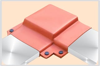
The seven, and the part each one takes
1. Straight bolted lap
Two bars overlapped and bolted, the commonest connection in a panel. Specify a moulded shroud. BUSBOOT in cross-linked polyolefin carries a 1.0 mm minimum wall at 12 kV rising to 2.5 mm at 36 kV; the PVC grade is thicker at every step, 2.00 mm at 12 kV and 4.50 mm at 38 kV. The PVC grade is the one carrying UL File E335936 and the ANSI C37.20.2 reference for switchgear application to 36 kV, and both grades come off again for the torque check.
2. Tee
A branch leaving a through bar at 90 degrees, at a feeder tap-off or a riser take-off. A tee that matches a catalogued type takes a moulding; anything else is a custom mould, for which no lead time is published and none is claimed here. For a tee already built and matching no moulding, cut sheet is the part that fits: GMHS gives flashover protection to 17.5 kV and GHHS to 36 kV, and the bus sheet datasheet sizes a 100 mm tee at a 450 x 325 mm cut, three to a sheet.
3. Elbow, in-plane bend
The bar turns in the plane of its width. No fastener, no change of section, so there is no separate part to buy. BUSTUBE is published as flexible enough for straight or angled bars without creasing, so the elbow is sleeved continuously with the run it belongs to. Size it on width plus breadth: a 100 x 10 mm bar sums to 110 mm, which sits inside the medium-wall GMB 100/38 window of 83 to 126 mm.
4. Riser or dropper
The run leaves the horizontal and goes vertical to a breaker chamber or an upper bus. The bend sleeves with the run, so the real decision sits at the top, where the riser lands. Stop the sleeve one overlap short of the landing and give the landing its own part, worked to the one overlap figure the range publishes: the bus sheet's 65 mm onto existing insulation after shrinking.
5. Edgewise turn, the hard way
The bar turns about its major axis and the flat face twists through the bend. The published flexibility claim covers straight or angled bars, which is not a claim about conforming to a twisted face, and nothing is moulded for a shape the bending machine defines rather than the drawing. Sheet it, or take the turn out at design stage: two flat bends and one bolted lap give back a geometry that has a part.
6. Flexible braid link
A laminated or braided link fitted between two rigid bars to absorb expansion and vibration. None of these parts belongs on it: a shrunk sleeve stiffens what was installed to move, an adhesive sheet does the same, and a shroud moulded to a rigid section will not stay seated on a link that flexes. Insulate the bars either side, treat the two bolted ends as laps, and space the braid to the bare figure — at 36 kV, 320 mm phase to phase, against 140 mm once the bar itself is on heavy-wall sleeve.
7. Bar-to-terminal landing
The bar bolts to a breaker spout, a CT primary, a transformer pad or an insulator stem. The envelope is bar plus terminal plus fasteners, usually with a step in section, so nothing catalogued against a bar size fits it. Cut sheet is the general answer, the cut extending a minimum of 100 mm onto each leg before it is shrunk. Two of the sixteen shroud types are drawn as a joint across a CT and one as a bar landed on a ribbed insulator, so ask for a type number before assuming the landing has no moulding.
The parts these seven shapes draw on
Thickness is quoted as the manufacturer quotes it: by voltage for the shrouds, by size code for the sleeve, by product code for the flat products.
| Part | Grade or series | Wall or thickness | Dielectric strength (min.) | Test method |
|---|---|---|---|---|
| BUSTUBE sleeve | GSC to 3.3 kV, GMB to 24 kV, GHB to 36 kV | 0.69 mm to 4.20 mm by size code | 22 kV/mm | ASTM D149 |
| BUSBOOT shroud, polyolefin | Cross-linked polyolefin, halogen free | 1.0 mm at 12 kV to 2.5 mm at 36 kV | 22 kV/mm | ASTM D149 |
| BUSBOOT shroud, PVC | Flexible PVC, UL File E335936 | 1.25 mm at 3.3 kV to 4.50 mm at 38 kV | 16 kV/mm | ASTM D149 |
| Bus sheet | GMHS to 17.5 kV, GHHS to 36 kV | 4.0 mm, 5.5 mm with the adhesive layer | not published | not published |
| Barrier board | GBBS-2, GBBS-3, GBBS-3A, GBBS-5A | 2.0 mm, 3.0 mm or 5.0 mm | 20 kV/mm | ASTM D149 |
Where insulated meets bare
Each of the seven ends somewhere, and the join between a covered region and a bare one is what an inspector looks at first. The discipline is overlap, and the range publishes one number for it.
- Overlap the existing insulation; never butt up to it. Bus sheet carries the only stated figure, 65 mm after shrinking, so 65 mm is the working floor for the rest.
- Cut long, then shrink. A sheet cut runs a minimum of 100 mm onto each leg before heat is applied, because the shrink pulls it back off the leg.
- Work the yield before ordering. A 100 mm tee takes a 450 x 325 mm cut, and a 1200 x 430 mm GHHS sheet gives three of them.
- A bar that ends rather than lands takes a cap, not a cover. BUSCAP is moulded in PVC, re-usable, and off again in minutes; no per-size dimension and no property table are published for it, so order it against the bar end and confirm the size in writing.
- Any gap left bare between two covered regions reverts the whole span to the bare clearance. Covering nine-tenths of a phase and leaving one lap open buys back nothing in panel width.
- A barrier between phases is a board, not a cover. GBBS comes 670 mm or 970 mm wide in 15 m lengths, cuts and drills without special equipment, and answers inter-phase flashover rather than contact with one conductor.
What this page does not establish
This page is about covering a connection, not about making one. Contact resistance, bolt torque, plating and the current the joint carries are busbar design questions, and no cover here changes any of them. A shroud over an under-torqued lap insulates a joint that will still run hot, and a covered joint cannot be inspected by eye.
What to read against this
- Busbar sleeve size chartGSC, GMB and GHB codes against width plus breadth, for the runs either side of every joint above.
- Air clearance, bare against insulatedThe millimetres at 12, 17.5, 24 and 36 kV — including the ones a braid link is still spaced to.
- Installing a busbar sleeveWorking order and heat, and where a sleeve has to be stopped short of a connection.
- How busbar insulation failsWhy a removable cover over a joint is worth more than a shrunk one at the first thermographic survey.
- Busbar insulationAll five parts in one index, and which region of a panel each one owns.
- Busbar insulation standardsANSI C37.20.2, IEC 216 and the ASTM methods behind the comparison table above.
Quote the joint, not the bar section
A connection cover is quoted against the made-up envelope: overlap length, fastener projection, any step in section, the phase spacing at the joint and the system voltage. Send those five figures with a photograph and the reply can name a part instead of asking for a drawing.